2.Hardware Connection
This chapter walks through the hardware assembly for the LAFVIN AIoT Starter Kit, including the ESP32-S3 main controller and the included modules.
Warning
Before starting assembly:
disconnect all power sources and do not wire the board while it is powered on
do not connect high-voltage external loads to the relay module until the board, firmware, and voice control path have already been tested successfully
Note
Use the included external power adapter only after the controller board and modules are connected. For first-time flashing, a USB Type-C data cable connected to your computer is usually enough.
GPIO Pin Assignment
The following table shows the main control pins used by each module:
Module Name |
Function |
GPIO Pin |
|---|---|---|
RGB LED |
Red, green, and blue channels |
GPIO4 GPIO5 GPIO6 |
DHT11 Sensor |
Data signal |
GPIO11 |
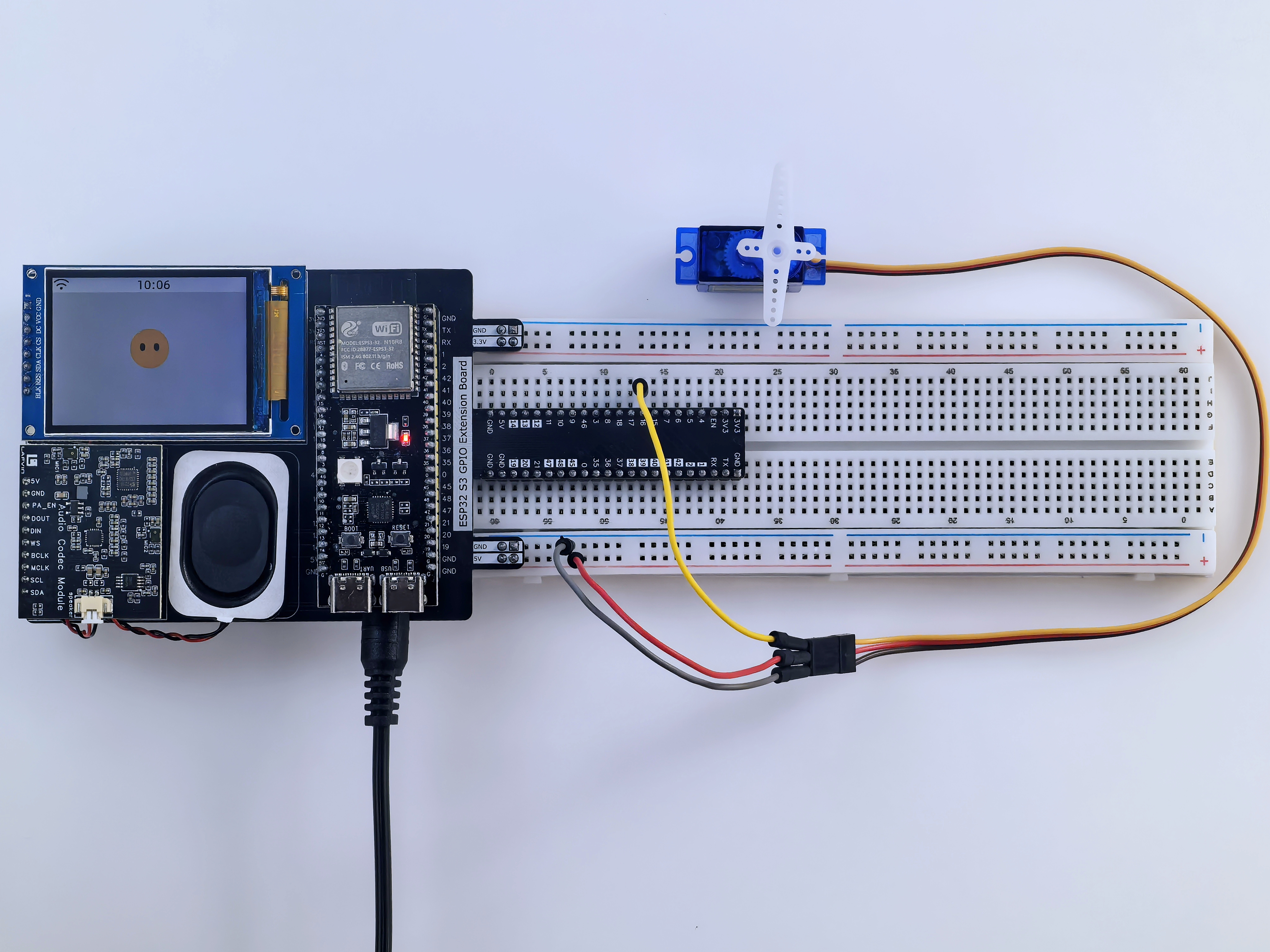
SG90 Servo |
PWM control |
GPIO16 |
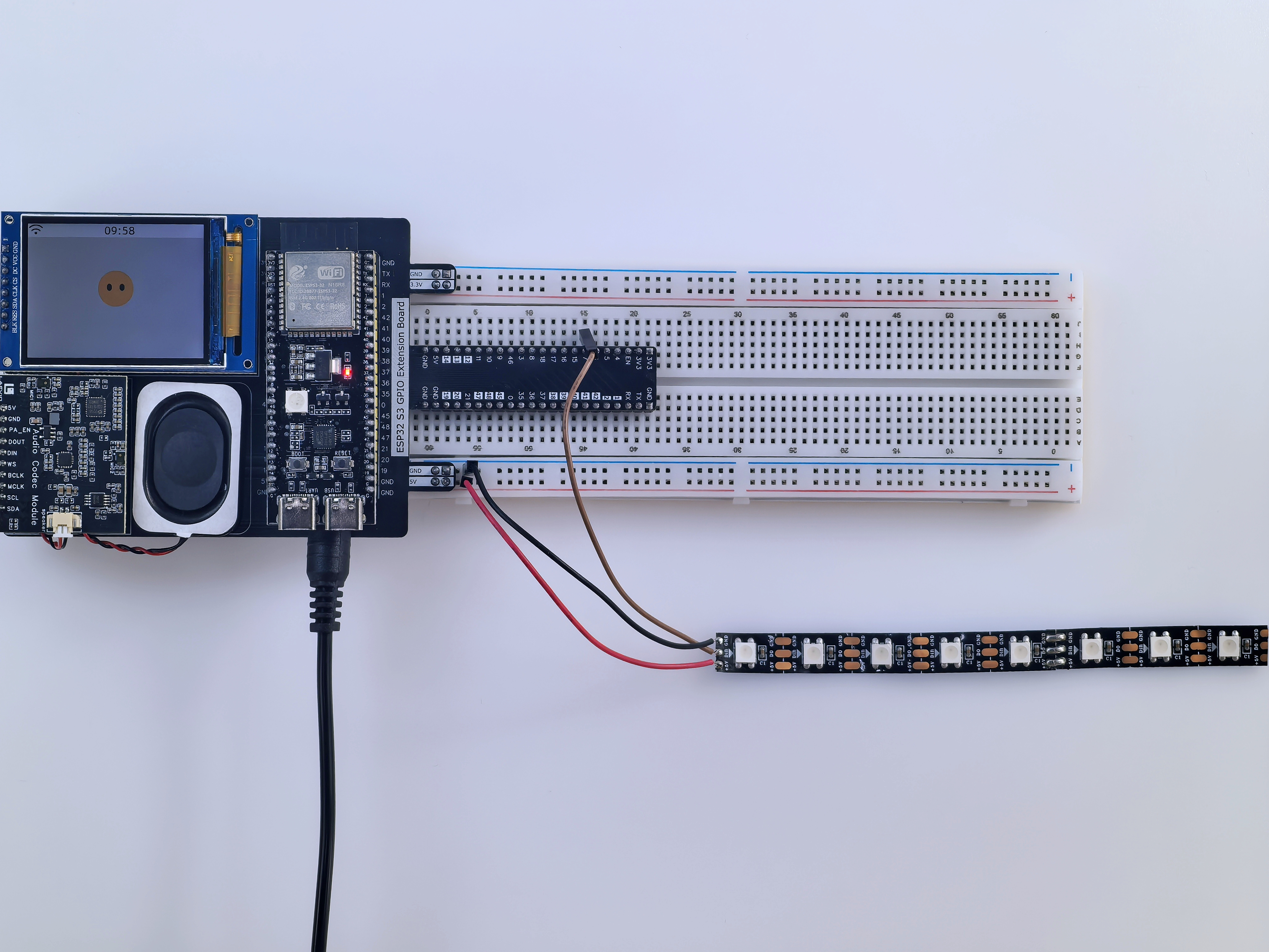
WS2812 LED Strip |
Data signal |
GPIO7 |
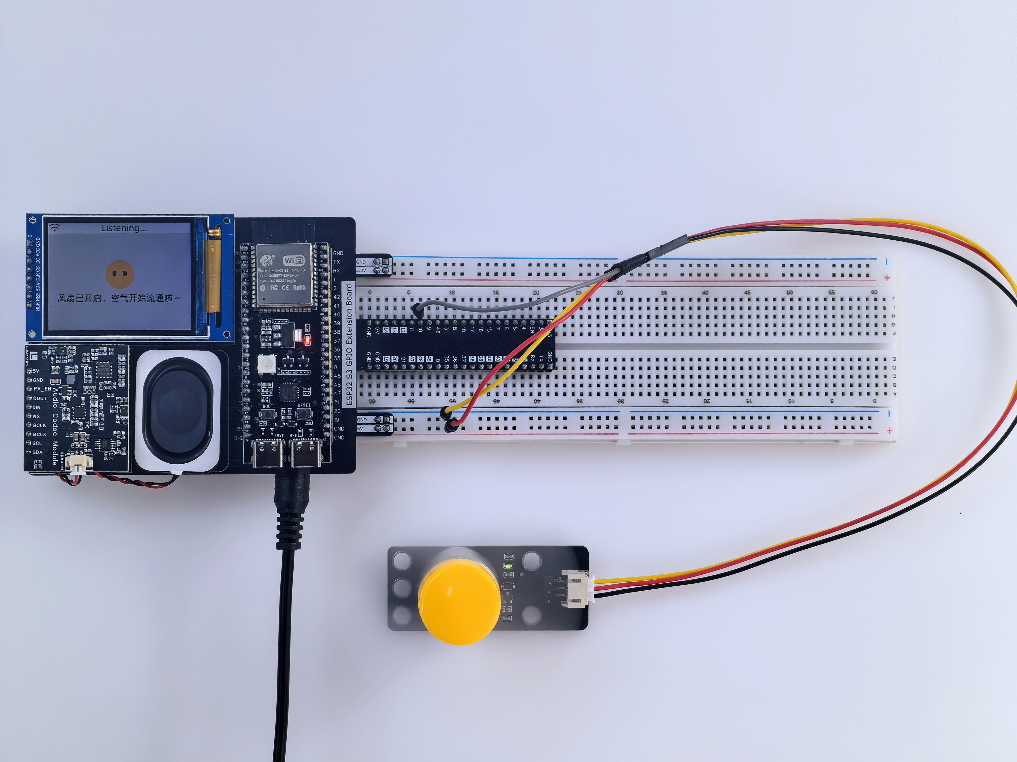
Fan Control |
Switch control |
GPIO10 |
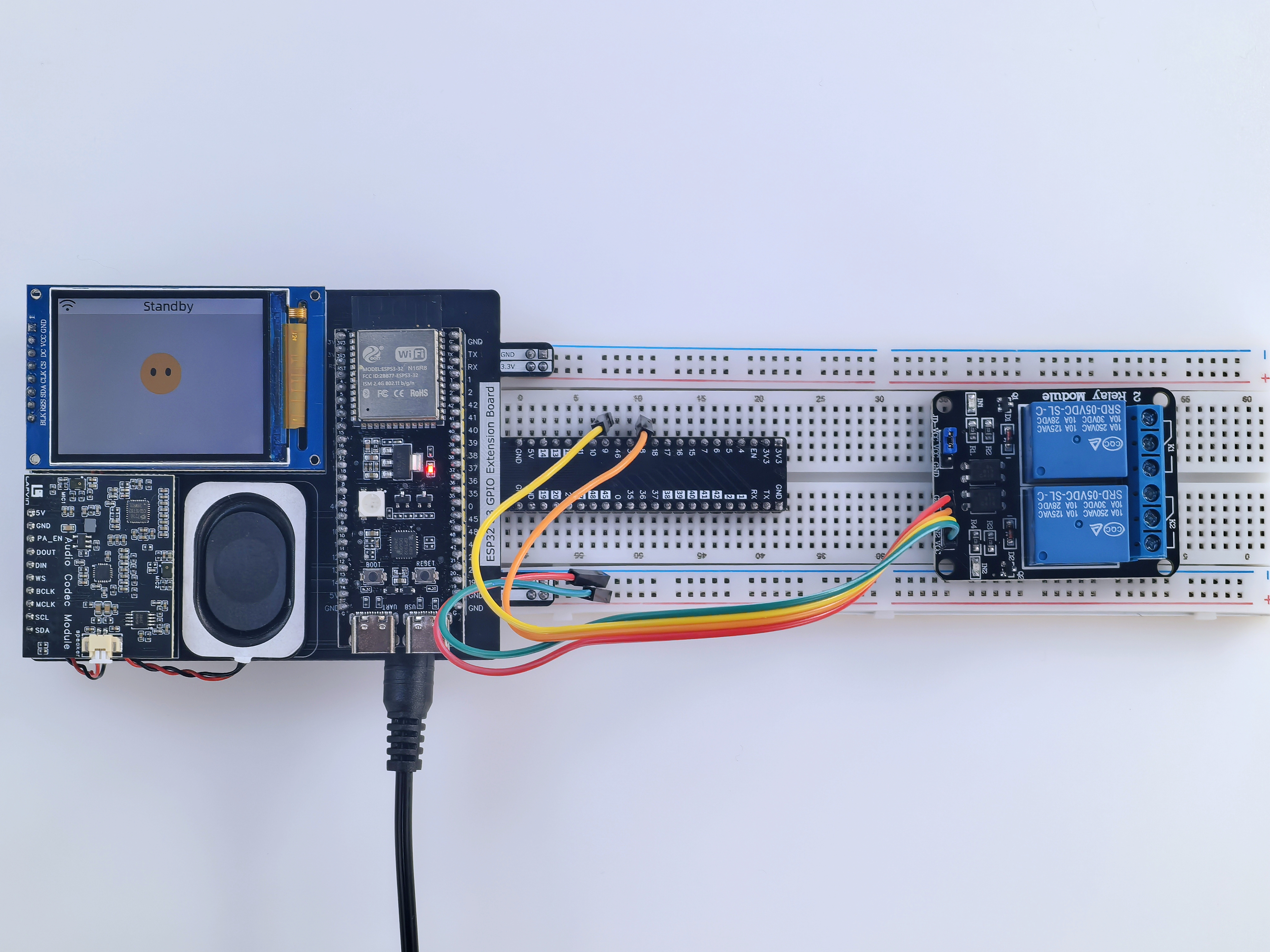
2-Channel Relay Module |
Control signals 1 and 2 |
GPIO8 GPIO9 |
Rain Sensor |
Digital signal |
GPIO15 |
Soil Sensor |
Digital signal |
GPIO17 |
Assembly Steps
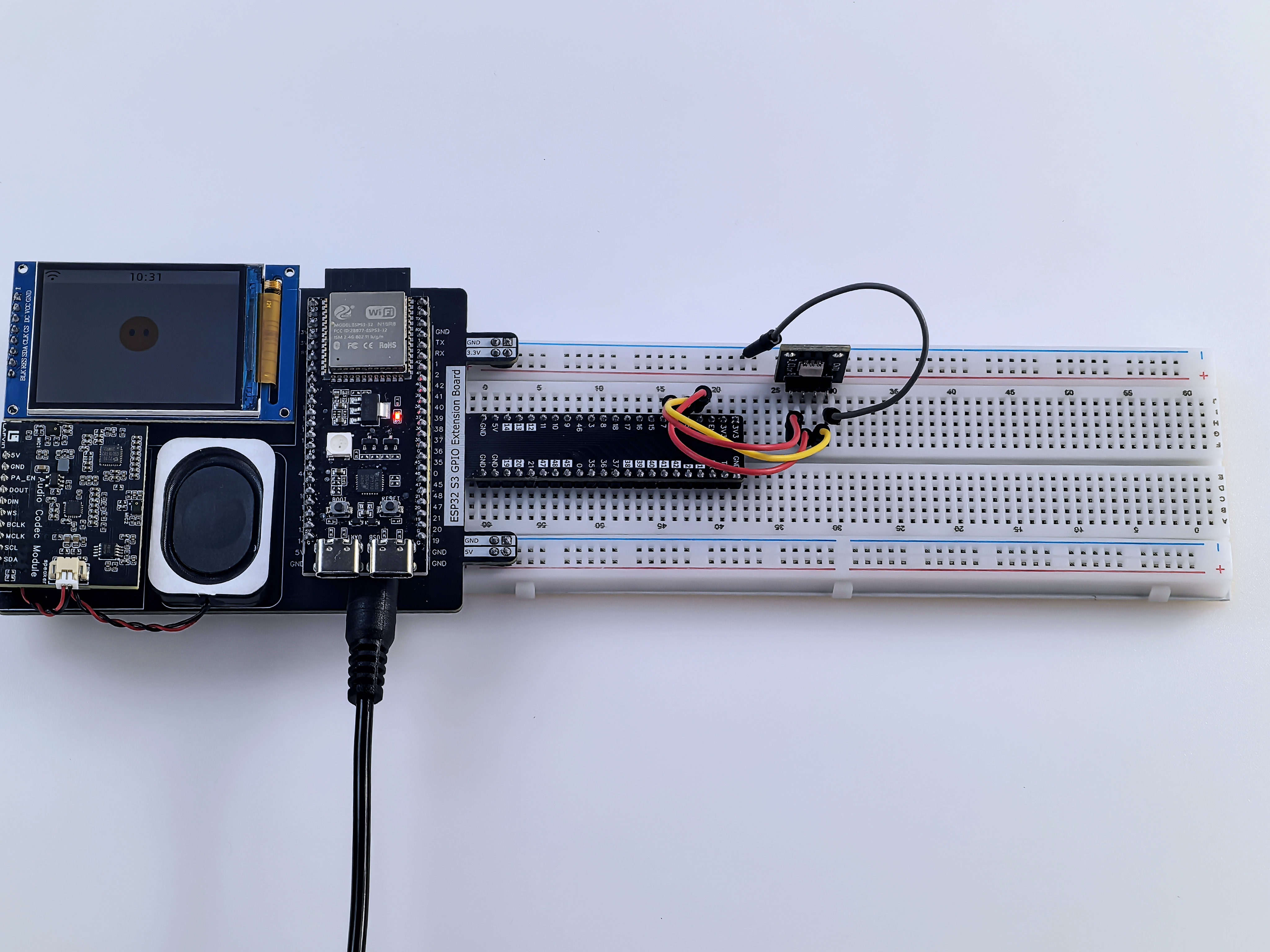
Step 1: Install the main controller
Insert the ESP32-S3 development board, audio board, and screen into the matching headers on the AI Chatbot IoT Shield.
Make sure the pins are aligned correctly and are not bent.
Insert the AI Chatbot IoT Shield into the breadboard.
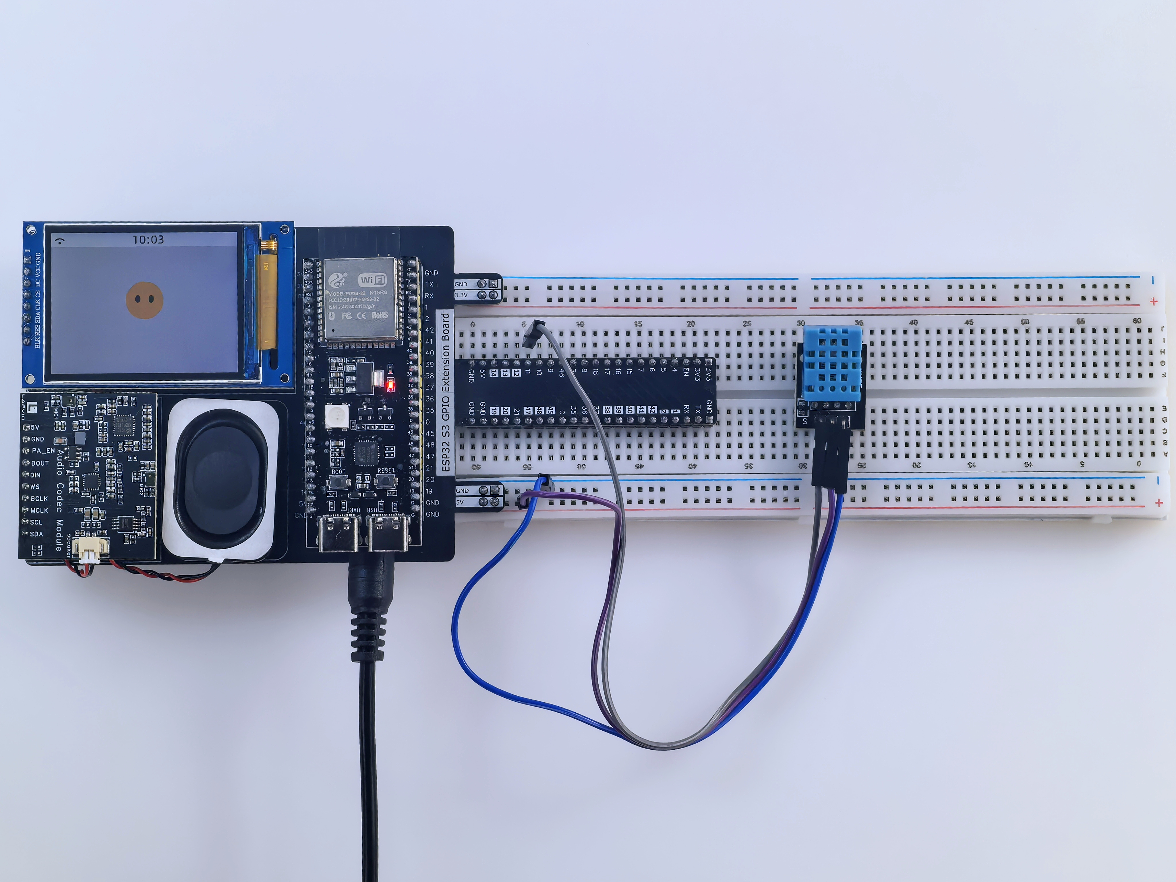
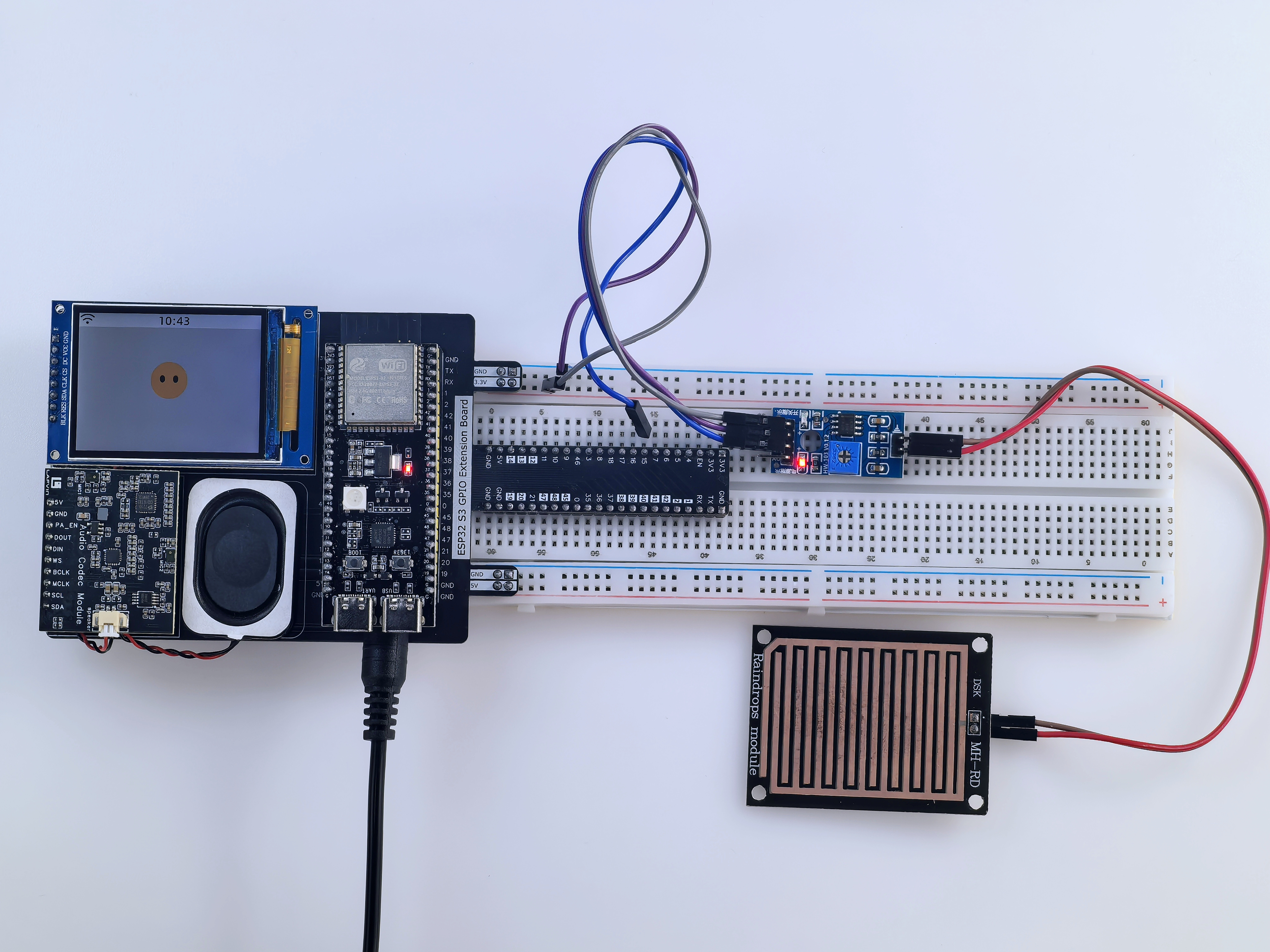
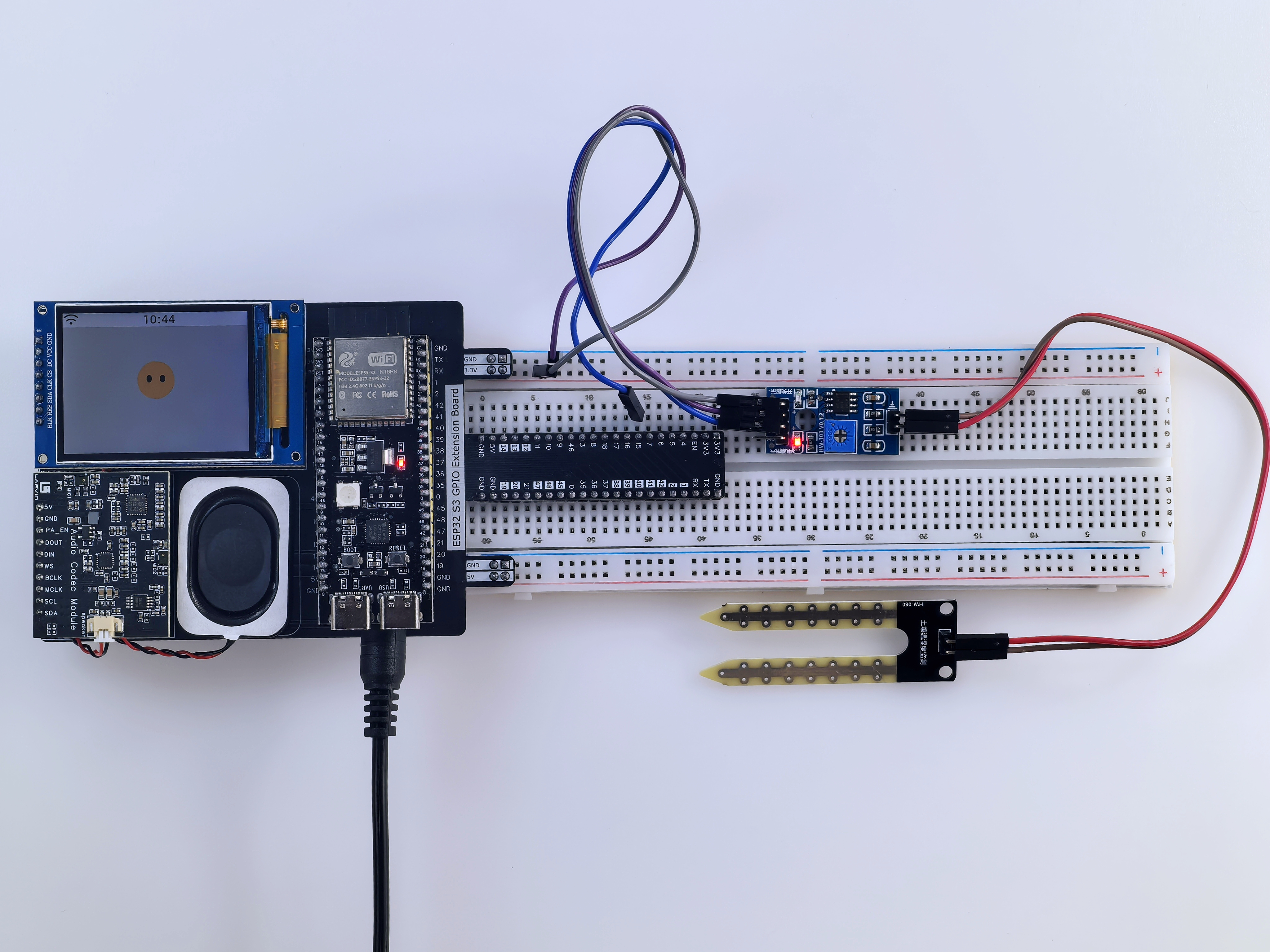
Step 2: Connect the sensor modules
Connect the DHT11 sensor according to the pin assignment table.
Connect the rain sensor and soil sensor.
Check that each connection is secure before powering the board.
Step 3: Connect the actuator modules
Connect the RGB LED module.
Install the servo and WS2812 LED strip.
Connect the fan and relay modules.
Step 4: Connect power for the first time
After the controller board and modules are installed, connect the included external power adapter.
Connect the USB Type-C data cable to your computer if you are preparing to flash firmware next.
Pre-Flash Check
Use this checklist before continuing to software setup and firmware flashing:
ESP32-S3 development board installed correctly
Audio board and screen seated correctly
All Dupont wires connected securely
Signal wires connected according to the wiring table
USB Type-C data cable connected to the computer
No external high-voltage load connected to the relay module
Basic Power-On Check
Connect USB power or the included external power adapter.
Confirm that the development board powers on.
If the board does not power on, disconnect it immediately and recheck the wiring and module alignment.
Tip
At this stage, verify only wiring and basic power. Perform voice, LED, and sensor function tests after firmware flashing, Wi-Fi setup, and backend binding are complete.
Next, continue with software setup and firmware flashing.